Mold-Tech Textures: Series, Draft Angle and How It Works
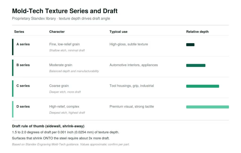
Mold-Tech is a proprietary texture system from Standex Engraving, not a public numeric standard like SPI or VDI 3400. Instead of a roughness scale, it is a library of texture patterns, organized into series and identified by numbers such as MT-11000, that reproduce grains, leathers, and geometric designs on molded parts. It is the dominant texture language of the automotive industry. Because it is pattern-based rather than roughness-based, Mold-Tech has no official conversion to SPI or VDI 3400, and its key design driver is texture depth, which sets the required draft angle. This page explains how the system works, the series structure, the draft rules, and how it compares to the numeric standards.
What is Mold-Tech?
Mold-Tech is a texturing system developed by Standex Engraving (formerly Mold-Tech), a global supplier of mold texturing services. Unlike SPI, which describes polish, or VDI 3400, which describes roughness on a numeric scale, Mold-Tech is a catalog of specific texture patterns. Each pattern has a serialized identifier and a defined character, from fine grains to deep, complex reliefs, and is reproduced on the mold cavity so that it transfers to the molded plastic part.
This distinction matters. A numeric standard answers the question "how rough or how smooth," with a single value. Mold-Tech answers a different question: "which exact pattern." Two parts could share a similar average roughness yet carry entirely different Mold-Tech patterns, because the pattern, the visual and tactile design, is the point. This is why Mold-Tech dominates applications where appearance identity matters, especially automotive interiors, where a precise, branded grain is part of the product.
Why Mold-Tech is proprietary, and why that matters
Mold-Tech is owned and maintained by Standex, which means the patterns are a proprietary library rather than an open published standard. In practice, this has three consequences for anyone specifying it. First, the authoritative reference is the Standex sample set, not a public table; a Mold-Tech callout points to a physical pattern plaque. Second, an "MT" number reproduced by a shop other than Standex is a copy, which may differ subtly from the original, so for parts with strict appearance requirements the original is worth the premium. Third, because the library is proprietary, cross-references to SPI or VDI are always approximate and unofficial.
The honest way to treat Mold-Tech is therefore to anchor on the physical sample and the Standex specification for the chosen pattern, and to treat any roughness equivalence as a rough guide only. This is the same principle that applies across mold texture standards: the physical reference wins over the chart.
The Mold-Tech series structure
Mold-Tech patterns are grouped into series, commonly labeled A through D, that move from fine and shallow to deep and complex. While the full library contains hundreds of individual patterns with their own MT numbers, the series give a useful mental map.
The A series covers fine, low-relief grains suited to high-gloss surfaces with only a subtle texture; the etch is shallow and the draft requirement minimal. The B series offers moderate grain that balances visual depth with manufacturability, and it is the workhorse of automotive interiors, appliances, and consumer products where a moderate, tactile grain is wanted. The C series includes coarser textures that emphasize grip, durability, or industrial styling, used on tool housings, equipment casings, and high-contact surfaces. The D series features high-relief or geometrically complex patterns for premium visual effect or a strong tactile identity, with the deepest etch and the highest draft demands.
Texture depth and the draft angle rule
The single most important engineering relationship in Mold-Tech is between texture depth and draft angle. A textured sidewall must have enough draft for the part to pull away from the pattern cleanly; too little draft and the texture drags, scuffs, or scratches the part during ejection, ruining the appearance and often forcing expensive tooling rework.
The widely used rule of thumb, based on Standex guidance, is to add roughly 1.5 to 2.0 degrees of draft for every 0.001 inch (0.0254 mm) of texture depth on sidewalls. A shallow A-series grain might need only a degree or so, while a deep D-series pattern can demand several degrees. Because deeper patterns require more draft, the texture choice is never purely cosmetic; it constrains the part geometry, and it should be decided together with the draft strategy at the design stage rather than added afterward.
The shrink-away versus shrink-on distinction
A critical detail that separates experienced specifiers from beginners is that the standard draft rule applies only to shrink-away sidewalls, surfaces where the plastic shrinks away from the steel as it cools, naturally creating clearance. Surfaces where the part shrinks onto the steel, gripping the core, behave very differently and require approximately three times the draft of the shrink-away rule.
This is because a part cooling onto a textured core clamps down on the pattern, and without substantial extra draft it cannot release without dragging across the texture. Lifters, slides, and other moving tooling components add further complexity, since their draft must be evaluated relative to their direction of action, not just the parting line. Shut-off conditions on textured sidewalls also typically need additional draft or special engineering to release cleanly. Missing this distinction is one of the most common and most costly texturing mistakes, because by the time it shows up, the steel is already cut.
How Mold-Tech textures are made
Mold-Tech patterns are produced primarily by chemical etching. A mask carrying the pattern is applied to the mold steel, and acid selectively etches the exposed areas to a controlled depth, transferring the design into the cavity surface. Etch depth is governed by the acid, the exposure, and the number of etching passes, and it is what determines both the visual depth of the grain and the draft the part will need.
Chemical etching suits complex, organic patterns, leathers, woods, and fine geometric designs, that would be difficult to produce by the EDM process used for VDI textures or by the mechanical polishing used for SPI. This is the technical reason Mold-Tech occupies the "pattern" niche while VDI occupies "roughness" and SPI occupies "polish."
The material changes the result
As with every mold texture standard, the molded polymer affects how a Mold-Tech pattern appears and how much draft it needs. Different resins do not behave the same on the same texture: a PA (polyamide) and an ABS molded in the same textured cavity can require different draft angles and can render the pattern with different sharpness. Semi-crystalline materials, which shrink more, tend to grip a textured core harder, pushing toward the shrink-on draft territory and demanding extra clearance. Glass-filled grades raise surface roughness and can blunt fine patterns. The practical rule is to confirm the draft and the appearance for the specific resin, not for texture in the abstract.
Mold-Tech compared to SPI and VDI 3400
Mold-Tech is one of three dominant mold texture standards, and the cleanest way to separate them is by what each describes. SPI is a US polish standard built around smoothness and finishing method. VDI 3400 is a German roughness standard built around EDM texture and a numeric Ra scale. Mold-Tech is a proprietary library built around pattern design and produced by chemical etching. SPI and VDI answer "how smooth or how rough"; Mold-Tech answers "which pattern."
There is no official conversion among them. A Mold-Tech pattern can be loosely associated with an approximate roughness, and therefore loosely with a VDI grade or SPI range, but the association is unofficial and should always be confirmed against a physical sample. For the detailed, sourced cross-reference, see the SPI to VDI 3400 to Mold-Tech conversion page, and the overview on the mold texture standards hub. For the draft side, see draft angle by texture grade.
Frequently asked questions
What is Mold-Tech?
A proprietary texture system from Standex Engraving: a library of texture patterns, identified by MT numbers and grouped into series, produced by chemical etching, widely used in automotive interiors.
Is Mold-Tech a numeric standard like VDI 3400?
No. SPI and VDI 3400 are scales of smoothness and roughness. Mold-Tech is a catalog of specific patterns; it answers "which pattern," not "how rough."
What are the Mold-Tech series?
Commonly A through D: A fine and shallow, B moderate grain for automotive and appliances, C coarse for grip and industrial use, D deep and complex for premium effect.
How much draft does a Mold-Tech texture need?
About 1.5 to 2.0 degrees per 0.001 inch of texture depth on shrink-away sidewalls. Surfaces that shrink onto the steel need roughly three times as much.
What is the shrink-away versus shrink-on difference?
Shrink-away surfaces pull away from the steel as they cool and follow the standard draft rule. Shrink-on surfaces grip the core and need about three times more draft to release cleanly.
How are Mold-Tech textures produced?
Mainly by chemical etching: a pattern mask is applied and acid etches the design into the mold steel to a controlled depth.
Does Mold-Tech convert to SPI or VDI 3400?
Not officially. Any equivalence is approximate, based on matching roughness, and should be confirmed with a physical sample.
Why choose the original Mold-Tech over a copy?
A copy of an MT pattern may differ subtly from the Standex original. For parts with strict appearance requirements, the original ensures the exact, repeatable grain.
Normative References & Sources
- Standex Engraving Mold-Tech — texture library and technical guidance: standex.com
- ISO 1302 — Surface texture indication: iso.org
- Mold-Tech texture depth and draft references (values approximate; confirm per pattern and resin).
Reviewed by Marcel Dias — Technical Editor. Mold-Tech is a trademark of Standex. Pattern, depth, and draft values are provided for reference and are approximate; verify against the original Standex specification and a physical sample before production. See our Disclaimer.
Leave a Reply